Do smart PDUs support environmental monitoring?
Yes, environmental monitoring is a standard feature of modern smart power distribution units (PDUs). At the rack level, smart PDUs connect to dedicated sensors to...


+86 15867381241
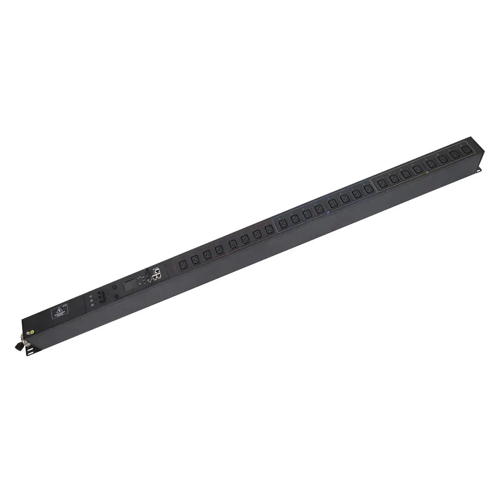
Outlet sequencing stops circuit breaker trips by spreading inrush current over time instead of letting all startup surges stack at once. When every device powers on simultaneously, their individual current peaks add up to a single large overload that can exceed the breaker’s rated limit.
A switched PDU solves this problem with programmable power-on sequencing: instead of activating all outlets at once, it turns them on in a predefined order with timed delays between groups. This spreads startup demand across a longer window, keeping total draw within safe limits. This guide explains the root cause of startup trips, how switched PDUs enable sequencing, and how to configure it step by step.
Rack power-on trips are almost always a timing problem, not a total capacity problem. The circuit can handle the full running load, but the combined peak of all startup surges pushes it past the breaker’s instantaneous trip threshold.
Every device draws a short, high spike of current when first energized, known as inrush current:
When dozens of devices share one circuit and all start at the same time, their individual peaks add together into one combined surge large enough to trip the breaker.
| Mechanism | Per-device contribution | Combined system effect | Why it causes trips |
|---|---|---|---|
| Ground-fault leakage | ~2 mA per VFD / LED driver / power supply | 20 devices = 40 mA total | Exceeds 30 mA GFCI trip threshold |
| Inrush current | 6–8× rated current for motors / transformers | Surges stack across all simultaneous starts | Magnetic breakers interpret the spike as a short circuit |
Staggered energization changes this math. A 200 ms delay between device starts lets the DC component of the inrush decay, so total peak surge drops to 2–3× a single device instead of the full sum. Fully sequential startup (one device fully energized before the next starts) keeps peak surge equal to one device’s rating.
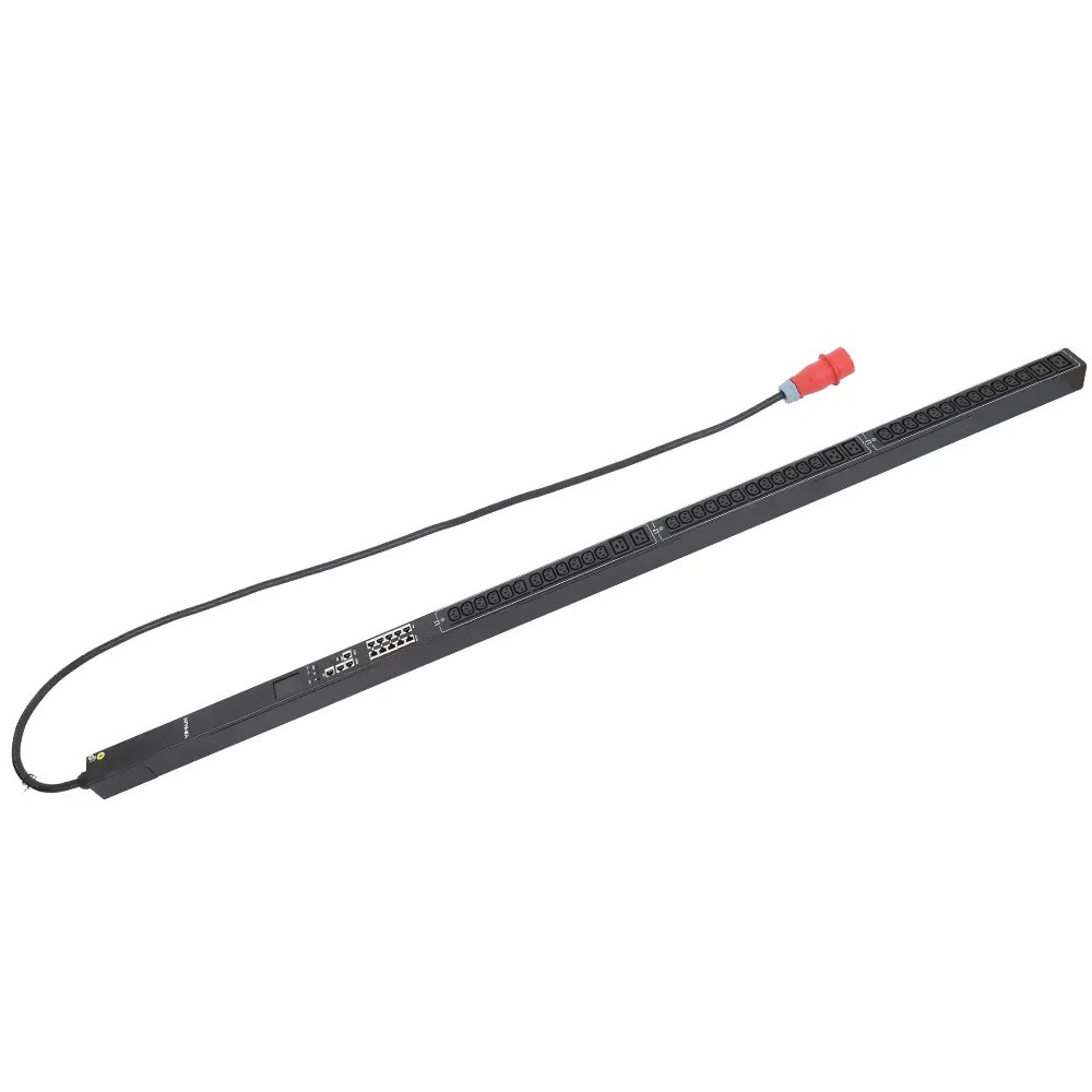
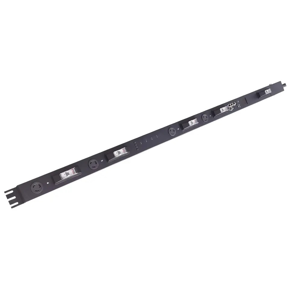
A switched PDU combines power distribution hardware with smart control circuitry, including a microcontroller, current sensing circuits, individual outlet relays, and a network interface. A PDU manufacturer designs these components to work together, allowing users to configure settings via a web UI, SNMP, or cloud platform, while the controller triggers each outlet independently.
This turns manual, error-prone startup procedures into a repeatable, automated policy.
Start with measured running current for all devices on the circuit, not nameplate ratings. Add a safety margin on top:
For circuits with large motors or transformers, size for startup surge rating first, not continuous current.
Breaker sizing rule: For continuous loads over 8 hours, derate the breaker to 80% of its rating per NEC. Always confirm breaking capacity exceeds prospective short-circuit current with a 10–20% safety margin.
Group outlets along two dimensions:
Standard rack startup order:
Delay lengths must match actual device behavior. Use on-delay timers for startup sequencing, and verify each group finishes its inrush before the next group activates.
Every device draws a short burst of extra inrush current at startup — motors can pull 6–8× their normal running current. When many devices start simultaneously, these surges add up. The combined peak can exceed the breaker limit even though the continuous running load is well within rating.
A switched PDU controls each outlet independently. Operators define a startup order and timed delays between groups, so each device finishes its inrush spike before the next group powers on. This keeps total draw under the breaker limit at all times.
Delays must match the actual startup behavior of the connected equipment. The goal is for each group to pass its peak inrush before the next group activates. Test and adjust timings based on real measured startup current.
A 25% margin above measured running load is a standard baseline. Use 20% for stable, cool environments with fixed loads, and 30% for warm enclosures or sites expecting load growth within 1–2 years.
Network switches boot first, followed by storage arrays, then application servers last. This ensures dependent systems have their upstream infrastructure ready before they power on, and spreads inrush across the startup window.