Can 1U switched PDU handle today’s data demands
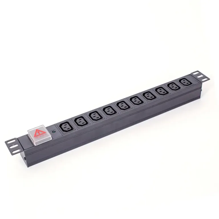
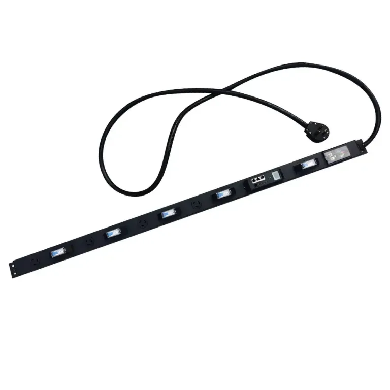
A 1u switched pdu delivers smart, reliable power and remote control, meeting today’s data center demands for efficiency, scalability, and uptime.

+86 15867381241
What is a PDU in networking? A Protocol Data Unit (PDU) is a single unit of information transmitted across a computer network. The term PDU is a specific name for a block of data at each layer in networking. Protocol data units are the fundamental building blocks for all communication.
As protocol data units travel through the network, the PDU structure changes. This journey transforms the PDU into a segment, a packet, and then a frame. Understanding this process is essential to the question, what is a network pdu? This single Protocol Data Unit is vital for all networking on a network.
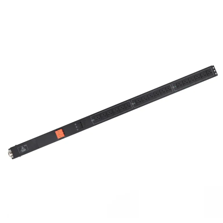
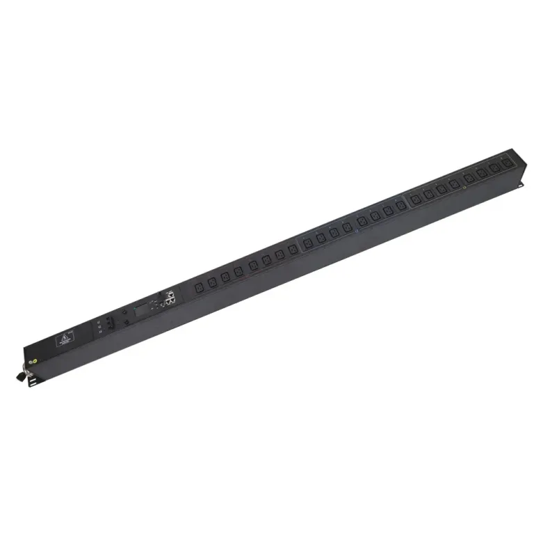
We recommend YOSUN’s Dual Input PDU, ATS PDU, and Intelligent PDU.
The journey of data across a network involves a fascinating transformation. A Protocol Data Unit (PDU) is not a single, static entity. Instead, it changes its name and structure as it passes down through the layers of the OSI model. Each layer adds its own control information, a process known as encapsulation. Understanding these different PDU types is the key to answering the question, what is a pdu in networking? This process ensures that data reaches its destination correctly.
At the top of the OSI model are the Application (Layer 7), Presentation (Layer 6), and Session (Layer 5) layers. For these three upper layers, the PDU is simply called Data. These layers prepare the information for its journey across the network.
Many common networking protocols operate at these layers.
The Transport layer (Layer 4) is responsible for host-to-host communication. It takes the data from the upper layers and breaks it into smaller pieces. The PDU at the Transport layer has two names, depending on the protocol used: Segment (for TCP) and Datagram (for UDP). The choice of protocol depends on the application’s needs for reliability versus speed. Both protocol data units serve the core function of the Transport layer.
The two main Transport protocols are Transmission Control Protocol (TCP) and User Datagram Protocol (UDP). They have significant differences.
| Feature | Transmission Control Protocol (TCP) | User Datagram Protocol (UDP) |
|---|---|---|
| Connectivity | Connection-oriented (establishes a connection first) | Connectionless (sends data without a connection) |
| Reliability | Highly reliable; guarantees delivery of protocol data units | Not reliable; does not guarantee delivery |
| Sequencing | Orders segments so data is reassembled correctly | No sequencing; datagrams may arrive out of order |
| Error Checking | Uses checksums and acknowledgments to fix errors | Uses a basic checksum for error detection only |
| Speed | Slower due to reliability overhead | Faster and more efficient |
| Header Size | 20-60 bytes | 8 bytes |
TCP Segments: A TCP segment is a reliable PDU. TCP establishes a connection before sending data, ensuring the receiver is ready. It uses sequence numbers to ensure all protocol data units arrive in order and acknowledgment numbers to confirm receipt. If a PDU is lost, TCP retransmits it. This makes TCP ideal for file transfers and web browsing, where data integrity is critical. The TCP header contains important fields like:
The size of a TCP segment is limited by the Maximum Segment Size (MSS). MSS defines the largest amount of data a device can receive in one segment. For IPv4, the default MSS is 536 bytes, while for IPv6, it is 1220 bytes.
UDP Datagrams: A UDP datagram is a simple, fast PDU. UDP is connectionless, meaning it sends protocol data units without establishing a connection first. It is faster than TCP but offers no guarantee of delivery, order, or error correction. This makes UDP suitable for real-time applications like video streaming or online gaming, where speed is more important than perfect reliability. The UDP header is much simpler, containing only source port, destination port, length, and a checksum. The Transport layer is fundamental to all networking.
The Network layer (Layer 3) is responsible for logical addressing and routing. It moves data across different networks to its final destination. The PDU at this layer is called a Packet. This is the PDU for IP (Internet Protocol).
To create a packet, the Network layer takes the segment or datagram from the Transport layer and encapsulates it by adding an IP header. This header contains crucial information for routing, most importantly the source and destination IP addresses. The IP address is the unique identifier for a device on a network.
The Internet Protocol (IP) has two main versions in use today: IPv4 and IPv6.
The IPv6 header was streamlined for better efficiency. For example, IPv6 removed the header checksum field. Routers no longer need to recalculate a checksum at every hop, speeding up packet processing. This task is left to the Transport layer’s own checksums. Additionally, the “Time to Live” (TTL) field in IP was renamed to the more descriptive “Hop Limit” in IPv6, but it serves the same function: preventing packets from looping endlessly on the network. The IP protocol is the backbone of modern networking.
The Data Link layer (Layer 2) handles data transfer between devices on the same local network. It ensures reliable communication over a physical link. The protocol data unit at this layer is called a Frame. This pdu is crucial for local networking.
The Data Link layer receives the IP packet from the Network layer. It then performs its own encapsulation. The layer adds a header to the front of the IP packet and a trailer to the end. This new pdu is the frame.
The frame header contains the physical addresses of the devices. These are called Media Access Control (MAC) addresses. The source MAC address identifies the sending device on the local network. The destination MAC address identifies the receiving device on the same network. This allows the frame to find its next hop. The IP packet inside remains untouched.
The trailer contains a special value for error checking. This value is the Frame Check Sequence (FCS).
This FCS process only detects errors. It does not correct them. Higher-layer protocols are responsible for requesting the retransmission of lost or discarded protocol data units. The IP packet is the core data being moved.
The Physical layer (Layer 1) is the lowest layer of the OSI model. It deals with the physical connection between devices. This layer defines the hardware, cables, and signaling needed to transmit data. The pdu at this layer is the most basic unit of information: the Bit.
This layer takes the frame from the Data Link layer and converts it into a raw stream of 1s and 0s. It then transmits these bits across the physical medium. The Physical layer does not care about MAC addresses or IP addresses. Its only job is to send and receive bits. This is the final step in sending the data from an IP packet.
The method of transmission depends entirely on the physical medium used for the network. The layer specifies how to turn digital bits into physical signals.
To convert bits into signals, the Physical layer uses encoding schemes. These are rules that define how a 1 or 0 is represented. Two common examples are Manchester and NRZ encoding.
| Encoding Scheme | How It Works | Key Feature |
|---|---|---|
| Manchester Encoding | A transition in the middle of the bit’s time slot represents the bit’s value. A high-to-low voltage change could be a 1, and a low-to-high change could be a 0. | It is self-clocking. The constant transitions allow the receiving device to easily sync up, but it requires more bandwidth. |
| Non-return-to-zero (NRZ) | The signal level itself represents the bit’s value. For example, a positive voltage can be a 1, and a zero voltage can be a 0. | It is simpler and uses less bandwidth than Manchester encoding. However, long strings of 1s or 0s can cause clock synchronization issues. |
Ultimately, these protocol data units work together to move information from an IP packet across the globe. Understanding how a pdu changes from a frame to a bit answers a key part of the question, what is a pdu in networking? Each layer, from the IP packet’s creation to its transmission as bits, plays a vital role. The journey of these protocol data units from a source IP to a destination IP is the foundation of all networking. The IP protocol data units are the heart of this process. The IP protocol is what makes the internet work. The IP address guides the protocol data units across the entire network.
Protocol data units do not just appear on a network. They are carefully built and then taken apart in a two-part process. This journey allows data to travel from an application on one computer to an application on another. The two key processes are encapsulation and decapsulation. Encapsulation wraps the data in the necessary control information. Decapsulation unwraps it at the destination. This system is the foundation of all modern networking.
Encapsulation is the process of adding headers and trailers to data as it moves down the OSI model. Each layer “wraps” the PDU from the layer above it. This process is like preparing a letter for mailing. You write the letter (the data), put it in an envelope (the segment), write the street address on it (the IP packet), and then give it to a local mail carrier (the frame).
The journey begins at the top layers and moves down.
A simple way to think about encapsulation comes from programming. A programmer might create a
Contactclass to hold a person’s name and email. The data (name, email) is kept private. The programmer provides public methods to access that data. This bundles the data with the rules for using it, which is conceptually similar to how a network wraps data in headers.
The table below shows what information each layer adds during encapsulation. Each header contains the IP address or other information needed for that layer’s job. The IP protocol is essential for this entire networking process.
| OSI Layer | PDU Name | Header Information Added | Example |
|---|---|---|---|
| Layer 4 (Transport) | Segment | Source & Destination Ports | Port 49152 → Port 443 (HTTPS) |
| Layer 3 (Network) | Packet | Source & Destination IP Addresses | Source IP: 192.168.1.2 → Dest. IP: 172.217.10.46 |
| Layer 2 (Data Link) | Frame | Source & Destination MAC Addresses | Source MAC: 00:1A:2B:3C:4D:5E → Dest. MAC: 00:9F:8E:7D:6C:5B |
Decapsulation is the reverse of encapsulation. It happens on the receiving device. As the data moves up the OSI model, each layer strips off its corresponding header. This process unwraps the data until it is back in its original form.
The journey for incoming protocol data units starts at the bottom and moves up.
This entire encapsulation and decapsulation cycle allows for organized and reliable communication across any network. The journey of a single pdu from an IP source to an IP destination relies on every layer doing its part. This process is the core of IP-based networking.
A Protocol Data Unit is not just a random block of data. It has a specific and organized format. The pdu structure typically consists of three main parts: a header, a payload, and sometimes a trailer. Each part has a distinct job. This organization allows devices to understand and process information efficiently as it travels across a network.
The header is the control center of a pdu. It contains essential information that guides the data to its destination. Each layer in the OSI model adds its own header with details specific to that layer’s function. This pdu structure is vital for routing and delivery.
For example, a Network Layer (Layer 3) IP header includes:
A Transport Layer (Layer 4) TCP header adds even more detail, like source and destination port numbers and sequence numbers for reassembling data.
The payload is the core of the protocol data unit. It contains the actual data being sent. This data comes from the layer directly above the current one. In networking terms, this payload is called a Service Data Unit (SDU).
The SDU from an upper layer becomes the payload for the lower layer. For instance, the Transport Layer receives data from the Application Layer. It wraps this data (the SDU) with a TCP header. The resulting segment is then passed to the Network Layer. The entire segment now becomes the SDU for the Network Layer, which treats it as its payload. This encapsulation process defines the pdu structure.
The trailer, or footer, is an extra section added to the end of some protocol data units. Its primary purpose is error checking. The most common example is found at the Data Link Layer (Layer 2). The PDU at this layer, called a frame, includes a trailer.
This trailer contains a field called the Frame Check Sequence (FCS).
This process ensures the integrity of protocol data units as they move across a local network.
Protocol data units are the essential building blocks for all networking. Each layer of a network uses a specific protocol data unit, from data and segments to packets and frames. Understanding the pdu lifecycle of encapsulation and decapsulation is key to managing any network. This knowledge fully answers the question, what is a pdu in networking. These protocol data units make modern networking possible across every computer network. A strong network foundation is crucial for all networking, ensuring the network runs smoothly.
A Service Data Unit (SDU) is the data from an upper layer. A Protocol Data Unit (PDU) is the SDU plus the header and trailer from the current layer. The PDU of one layer becomes the SDU for the layer below it during encapsulation.
Each OSI layer has a specific job. A PDU changes because each layer adds its own control information (a header) to the data. This process, called encapsulation, ensures the data has the right instructions for routing, addressing, and error checking at every step of its journey.
A Power Distribution Unit is a different type of PDU. It is a piece of hardware that manages and distributes electricity to servers in a data center. It is not the same as a Protocol Data Unit in networking. YOSUN is a professional manufacturer specializing in these data center Power Distribution Units.
The packet is the most important PDU for the internet. As the PDU for the Network Layer, the packet contains the source and destination IP addresses. Routers use these IP addresses to send data across different networks, making global communication possible.
Discover Why an Automatic Transfer Switch PDU Is Indispensable Now
Unmissable Advantages: The Power of Auto Transfer Switch PDUs Revealed